Joe's Makerbot is now Joe's 3D Workbench. http://joes3dworkbench.blogspot.com/
This has been a long time coming. I avoided it for many technical reasons, but I now feel it's time.
Joe's Makerbot (this blog) will remain with it's history and posts, but I will no longer be updating it. From now on all posts related to making, designing, and teaching will be on Joes3dWorkbench.blogspot.com. I hope you'll all visit me there. I will also occasionally post my more editorial thoughts on 3DHacker.com's blog.
http://joes3dworkbench.blogspot.com/
Showing posts with label product testing. Show all posts
Showing posts with label product testing. Show all posts
Friday, December 6, 2013
Monday, November 11, 2013
Testing 3D Printed Dice Fairness - New Hollow Dice
 Using the information gathered last time I modified a dice I made in tinkercad way back when and made a die that I figured would be sufficiently fair. Hollow like before this die has totally sharp edges. But because I can't leave well enough alone I made another that had flat corners, or "truncated" to use a geometric term.
After 30 rolls the chi-squared number for the totally square one was 14 placing it among the best of the last bunch. The chi-squared number for the truncated one was 30 placing it among the worst. Fine, I've learned my lesson. Don't mess with what works and go with the data.
You can download the square hollow dice on thingiverse.
Friday, October 11, 2013
Testing 3D printed dice fairness - Chi-Square Data

- Dual Extrusion Die - Chi Square = 20
- Customized Die 20% infill - Chi Square = 18
- Customized Die solid - Chi Square = 28
- Cone Holes 20% infill - Chi Square = 12
- Cone Holes solid - Chi Square = 28
- Normal 20% infill - Chi Square = 24
- Normal solid - Chi Square = 40
- "Balanced" Die 20% infill - Chi Square = 22
- "Balanced Die solid - Chi Square = 32
- "Worthless" Die 20% infill - Chi Square = 16
- "Worthless" Die solid - Chi Square = 12
Which means according to the Pearson's chi-square test any of these 3D printed dice are sufficiently balanced to use. And this thing is supposed to have only a 5% failure rate, so there you go. 3D printed dice can be used as dice.
Do I believe it? It seems to me that to get a score of 55 a dice has to be severely imbalanced, so I look at this data as a scale of balance. Which of these dice are most balanced? Well according to my results the list in order, from most balanced to least, is: Cone Holes Infill, Worthless Solid, Worthless Infill, Customized Infill, Dual Extrusion, Balanced Infill, Normal Infill, Cone Holes Solid, Customized Solid, Balanced Solid, Normal Solid.
It pleases me that the so called "Worthless" die ranked so highly regardless of fill. But it bothers me that so many of the solid dice ended up ranked lower because I really like the way they feel. Perhaps the lighter weight allows them to bounce and explore the space better. Which, again, explains why the worthless dice is not so worthless as it has a forced empty center. Many of the highest ranking designs are sharp cornered, but so is the lowest ranked, so rounded or sharp corners don't seem to matter. That speaks well for the chances my hollow die (which I didn't include in this test because I was expecting the rounded corners to be bad). The Customized dice also did fairly well with infill, so that opens up all sorts of options.
Now that these experiments are done I'll be selling them if you're interested in having some.
Now that these experiments are done I'll be selling them if you're interested in having some.
Conclusion: According to the Pearson's chi-square test a 3D printed dice is sufficiently balanced, but it seems that dice with low infill are more balanced. Who'd have thunk?
Monday, October 7, 2013
Testing 3D printed dice fairness
 It's been a question on my mind for a while whether a 3D printed die can be fair and balanced? The reality is that the dice you buy aren't necessarily fair, so making a 3D printed dice fair could actually be an advantage. For a while I wanted to build a clever machine to automatically test dice, but that's been a project I never had time to explore. Finally I decided to print a bunch of dice and just roll away.
At first I printed a 4 dual colored dice, 20% infill and 2 shells. Not knowing there was a proper way to go about this I just stared rolling and recording until I felt a bias turn up. After collecting over 200 data points it seemed to me that there was a bias towards the low numbers for some reason, so I decided that I should try a single color dice.
Next I tried 6 copies of the customizable dice, 20% infill, 2 shells. I wanted this one to work, and the bias seemed somewhat less.
However I theorized that 100% infill would be better. So I printed 5 copies 100% infilled. Only the bias seemed to get worse, 1 hardly ever came up. So I inspected the dice and found discovered there was a seam running up the corner between the 1 and 4 side. Other slicers try to negate this by jittering where they start and end perimeter loops. MakerWare thinks they got rid of the seam so they done, which means when they're wrong you get a zipper up one side.

Finally I did some research and discovered that there is a prescribed method for these thing that involves only 30 rolls and does not involve "seems like" analysis. I also discovered that commercial dice aren't always fair and that the rounder dice make imbalance more pronounced. With this in mind I threw away the old data, sought out some flatter dice (for which there aren't many on thingiverse) and started to properly gather data, which I will report on in part 2.
Tuesday, October 1, 2013
New Makerware first impression
Big news, there's a new version of Makerware out. When I decided to adopt Makerware as much as possible I've only found a few little issues. Just last week I found another one, a model that sliced really strange even tho it looked fine in the software. So I've got a lot of tests to run.
 Print estimates info is nice, too. I think I'm going to leave this on all the time.
I like the sacrificial walls they've added to dual prints. It would be nice to turn those on whenever I wanted for narrow prints so I could say goodbye to the sacrifical tower.
To sum up:
The good:
The first thing I noticed is that filament diameter is still not editable without editing a text file. No profile editor UI yet either. So that's strike 1 and 2.
But there are some new options concerning dual extruders and support materials. Those will be fun to play with. However, now that I'm using GCode temp override half of that doesn't matter. But the new stuff about generating good paths with the end of sacrificial towers I'm excited to play with.
Then I noticed that opening a new file opens a whole new program window, which is annoying for me because I have 2 monitors and for some reason it wanted to open them on the wrong one my entire session. I got in the habit of using open because I didn't like how the new option used to do this if I wanted to clear the scene to slice another print. So kudos for being consistent, I guess. Too bad they chose the wrong constancy. (Note, I'd rather just clear the current scene than open a new window, if I wasn't being clear.)
Well, at least their fancy new preview mode will allow me to... uh.. where's that fancy new preview mode? There's no button, no menu item. Turns out you have to check the "Preview before printing" button, even if you're exporting to a file, before you hit the Export button in the Make menu. If you fail to do this you do not get the option later without re-slicing the model. But once I found it it was enough to tell me that Makerware is still choking to death on the Guy Fawkes pin, so thanks for saving me that trouble. In fact this preview has helped me find and predit problems in 3 other files in my explorations, so while Makerware still can't slice worth a darn, at least it'll warn you before you print.

I like the sacrificial walls they've added to dual prints. It would be nice to turn those on whenever I wanted for narrow prints so I could say goodbye to the sacrifical tower.
To sum up:
The good:
- Preview is good, when you can find it.
- Print estimate info.
- New dual print supports.
- New dual print options.
- New dual print sacrificial walls.
The bad:
- Still can't edit filament diameter without making a new profile.
- Still can't make a new profile without editing a text file.
- Still runs into problems with geometry that looks good but slices bad.
- I'd love to have the sacrificial walls on any print I want.
- When exporting to file (at least) I'd love to be able to pull up the preview when the slicing is done. Maybe don't close the status window when the process is done and let me pull that option up myself.
Welp, I'm off to write an e-mail to Makerbot suggestions.
Friday, August 16, 2013
How small can text print?

This is based on the measurement that 1 point = 0.37594 mm. This is also based on MakerWare which does an excellent job with text, better than Skienforge did.
Thursday, August 15, 2013
Building a sacrificial tower to fix your prints.

When asking Joe Sadusk about it he suggested it was the time spend on each layer or number of shells, since I was printing with just 1. So I thought I'd do a little experiment and see what I can see. I tried different shells and different minimum layer times. The results were mostly the same, changing minimum layer times didn't fix a thing, adding shells only fixed a little.


I was impressed that in Makerware I was able to add a 20mm test cube from the menu then scale it non-uniformly to make it as tall as the piece but thin so it doesn't waste much plastic.
The result, the print on the right, was the best of the lot. You can see the sacrificial pillar there too, it kinda detached and if it weren't for the anchor would have been useless, but the anchor kept it in the general area where it could serve as a sort of brush while the layer cooled. This is a filthy workaround, but it works for now. The real solution in my opinion would be if the bot were equipt with a brush and the minimum layer time didn't slow down the print but instead moved the nozzle away for any extra time. But until then I think I'll keep the sacrificial tower in mind.
Monday, July 22, 2013
Stress test? Pshaw
TurnRock's Super Stress Test is designed to push the limits of what home 3D printing can do... theoretically. In reality this was hardly a test at all for my Makerbot. I know I keep lauding it here, but I am really impress with the small details that MakerWare handles so well. So to really stress the test I reprinted the test at 75% and 50% of the original size to see what fell apart. Unfortunately I didn't pick colors that photographed well so I'll just have to describe it.
 At 100% every detail of the model is present. The lettering, the thin fingers on the one side, the sloping ramp, the wire-frame ball, the thin wall bridging, the standing waves, the arches, the tiny cylinders, the hollow sphere... everything. At 100% Joe's Makerbot can handle it all. There were 2 strange things. First of all there were only 2 tiny cylinders where the original had 3 and the thin vertical wall in the corner of the rectangular hole didn't print, but the top managed to overhang itself just fine so that I thought it was part of the original design.
At 75% I accidentally broke the spiraling cones when I removed the print, but they printed well. The problems were the wire-frame ball fell apart, the lettering is illegible, and the tiny fingers were falling apart, some of them. But otherwise the rest of the details were present. In fact there are 3 tiny cylinders at this point and the vertical wall in the corner is back and complete.
At 50% it's amazing how much detail is still there. The lettering is still gone, the tiny fingers were gone, the cylinders were all merged into one blob, and the wire-frame ball was... actually it looks a little better at this level than 75%, but it was still a mess. But besides those few things the rest of the details were still, surprisingly, in tact.
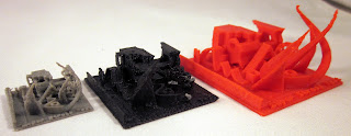
I think that this "stress test" would be a good way for a designer to study to know how far they can safely push design and have it be successful on home 3D printers. Go any smaller than what this test did on your details and you're asking for trouble.
Wednesday, July 10, 2013
A second shot at a Modibot
After my last go Wayne Loosey actually contacted me and asked if I'd like to test a few accessories for modibots on my next go. Well that motivated me to give this another shot.
 Did a couple of things different this time:

- Scaled everything to 130%. This was to hopefully increase wall thickness and fudge the tolerances. Mostly successful, except how the bot is big.
- Tried standing all ball-on-one-side-socket-on-the-other parts vertically on the ball to further minimize contact with the support material. Failed every time and I tried many variations including adding my own supports. There just wasn't enough holding the part to the platform and they wiggled themselves to spaghetti.
- Anything that had to be 100% supported (no flat surfaces to print from) was elevated 5mm off the build platform. The theory was that when the balls were right on the build surface the support material under them didn't have enough layers to form under them. It was partially successful, but I discovered that while better than when using ABS the balls joints still weren't really round and had to be sanded into shape.
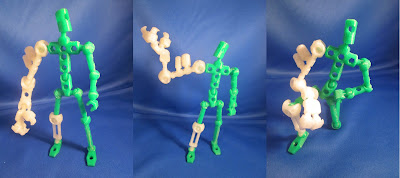
During assembly I only had 3 breaks, the left hip socket and two of the claws. The claws still had enough to hold on well but the hip socket only held on long enough to take some pictures.

Got to print the arm from one of the kickstarter kits. Used my white PLA for that. I call the middle one "lament of the cyborg".
The result was super posable and despite some roughness with PLA against PLA (it doesn't seem to slide like ABS and it definitely doesn't flex), after a little sanding to make the ball joints rounder it all fit almost perfectly. However in the arm accessory kit there was a new kind of joint, one that came around the ball on 2 sides instead of 3 and the result was the best joint of the bunch for hold, pose, and assembly. I would say to Wayne that all sockets need to have a split down the side separating it into two halves so it flexes during assembly. It doesn't need to be fully split like the wrist joint (or what I'm using as a wrist joint anyways) just a 2-3mm slit down the third side to add some flex is all. I would also say that increasing the joints to 130% would help. Not everything needs to be bigger, just the joints, tho the result might be a bit funny looking, I don't know.
I'll be sending a print to Wayne Loosey here soon with supports attached for educational purposes. Maybe we'll see a completely home 3D printer friendly version one day.
I would also say to Makerbot why do I have to edit a text file to adjust filament diameter?! I'm gonna keep harping on this until they fix it. That is the only setting I feel like I need exposed.
In other news I'm very close to finishing Makerbot Project Blueprints, but things have taken a pause on my end while I wait for the proofers to check the last couple of chapters. I accidentally listed url wrong on the associated files making it impossible for them to proceed until I told them what it should have been. But we're past that bump now and hopefully finished with the 2nd draft quickly, then on to the final print layout. Exciting stuff.
Tuesday, July 2, 2013
Home printing a Modibot
I've mentioned Wayne Losey's Modibot before (and subsequent rantings about using 3D printing for manufacture). The basic "Mo" Modibot is available for download on 3DBurrito. So how well does a model created for SLS printers to use as little material hold up when printing on a home 3D printer?
 The final verdict is this is as challenging a print as I've ever done, and it's not perfect yet. I credit MakerWare and a well tuned Makerbot for getting it to work as much as I did, but I also credit the shortcomings of MakerWare for where it didn't work.
The first challenge was orienting the pieces for print. I wanted to, as much as possible, avoid supports on the balls and avoid completely supports in the concave joints. I decided to stand up the body and hips, but lay down the rest of the parts.
I started with an ABS print but with my known issue with abs and supports, particularly with spheres, it didn't work. In fact every piece had problems and basically fell apart. So I pulled out some PLA donated by Andrew Mazotta and gave that a shot.
 This time the pieces printed better. Cleanup of the supports was an expected pain. But assembly was too tight. Burs left over from the supports on the ball joints caused some problems that could be fixed with a little sanding, but it was clear that even when it did work the joints were being strained more than they should. In fact both ankles snapped upon assembly. It was pretty clear to me that increasing filament diameter one or two hundredths for a millimeter would fix it. Gosh it would be nice if MakerWare made that easy.
The final result held together just long enough to take a picture. It's possible that scaling it up an additional 20% would fix some of the thickness issues. Dialing in the filament diameter would fix others. And making a version lie Beco Blocks designed for home 3D printers would defiantly fix a lot of the problems. But over all I'd call this experiment "promising, but not completely successful."
I've actually been in contact with Wayne, the creator of the Modibot, and he's expressed interest in making this work, so expect this experiment to continue.

The first challenge was orienting the pieces for print. I wanted to, as much as possible, avoid supports on the balls and avoid completely supports in the concave joints. I decided to stand up the body and hips, but lay down the rest of the parts.
I started with an ABS print but with my known issue with abs and supports, particularly with spheres, it didn't work. In fact every piece had problems and basically fell apart. So I pulled out some PLA donated by Andrew Mazotta and gave that a shot.

The final result held together just long enough to take a picture. It's possible that scaling it up an additional 20% would fix some of the thickness issues. Dialing in the filament diameter would fix others. And making a version lie Beco Blocks designed for home 3D printers would defiantly fix a lot of the problems. But over all I'd call this experiment "promising, but not completely successful."
I've actually been in contact with Wayne, the creator of the Modibot, and he's expressed interest in making this work, so expect this experiment to continue.
Wednesday, June 26, 2013
Reevaluating MakerWare
After giving Makerware a public lashing I found myself in contact with Joe Sadusk who is a developer for MakerWare at Makerbot (this blog attracts the Joes doesn't it?) We spent the weekend talking about MakerWare, the shortcomings it had and Sadusk defended MakerWare extremely well.
So I decided to give MakerWare another shot and since I needed to test out the 3DHacker test object I decided this would be a great test. I also decided test out the new raft just for fun. I made a previous iteration of the 3DHacker test object on ReplicatorG/Skienforge but what came off MakerWare/MiracleGrue just blew me away. Unfortunately pictures of the RepG one I printed aren't really useful since I changed many elements between the two versions but MacGyver printed a version that is good for reference.


So I decided to give MakerWare another shot and since I needed to test out the 3DHacker test object I decided this would be a great test. I also decided test out the new raft just for fun. I made a previous iteration of the 3DHacker test object on ReplicatorG/Skienforge but what came off MakerWare/MiracleGrue just blew me away. Unfortunately pictures of the RepG one I printed aren't really useful since I changed many elements between the two versions but MacGyver printed a version that is good for reference.

Let's brake it down zone-by-zone.
- The Raft came off the build platform well, but didn't come off the build very easily and bottom of the print where it attached to the raft was... weird. Kind of the texture of oatmeal. Not sure how to describe it. Now normally the raft is an assist to the supports, it's not meant for this sort of thing so I do want to see if it handles supports better.
- Overall the MW version had much better surface finish. I couldn't spot any gaps where layers started or ended, the layers were smooth and blended together. It just had an over-all better "look".
- The overhangs amazed me. 45 looks great, 60 looked great, 70 looked good. A 70 degree overhang looked good. That's not supposed to happen.
- The bridge on the H worked better than I've ever been able to get it to in RepG.
- MW pushed the detail on the fragility test behind the H much further than RepG did, to the point where they were so fragile they broke off when I was handling it, but it did try it and they held to the end of the print.
- The two pieces joined perfectly, but that's just luck. If my filament had swollen or had been from a different supplier this wouldn't have gone well.
- The increasingly narrowing wall Makeware took to a single wall and connected it. (You can see on MacGyver's print, second to last picture, how RepG gives up and turns it into a gap.)
- The vertical holes look great on this one. RepG for some reason trimmed the tops on most of them.
- And it does a 45 degree solid fill by default which I prefer.

Honestly, I'm impressed. However, this model was done with only the perimeter shell to make for a good picture and to avoid the "spurs" or little gaps that are left when an area gets too narrow for an inner shell to fill in all the way. So I did another one with 3 shells and discovered a few things:
Okay, I'll admit it, I'm going to start using MakerWare more often. True you can't edit the settings very much but when it just works like this who needs to? Frees me up to design cool stuff. But there are a few things I will complain about:
- This time the 70 degree overhang failed entirely. Apparently extra shells cause overhangs to curl more. (Probably true for RepG because I'd seen it many times before and almost never printed with less than 3 shells.)
- MakeWare generated less spurs than RepG. For instance around letters removed from a flat surface like the "acker" on the test object there are many places that generate spurs. But Makerware generated less.
Okay, I'll admit it, I'm going to start using MakerWare more often. True you can't edit the settings very much but when it just works like this who needs to? Frees me up to design cool stuff. But there are a few things I will complain about:
- I don't like the blobby anchor. I worked hard to kill it last time, at least this time it isn't making a blob on the side of my print but I hate having to break something away on every print when there are better alternatives.
- I don't like having to create a custom profile for every filament diameter. Filament swells or shrinks with humidity and what works for Makerbot in NY by the sea does not work for Joe's Makerbot in the middle of the great American desert. I don't care if we get a gui to change all the options I want this one exposed on the GUI same as shells, temp, or speed.
But really, these are minor things to put up with for the benefit. Well done Joe Sadusk. It's hiring people like you that makes Makerbot awesome.
Tuesday, May 28, 2013
Makerbot vs uPrint
My day job has got a uPrint 3D printer by Stratysis which is also a FFF machine like my Replicator, so I decided to print amodel out on both of our machines to see which one looks better.
 The final judgement is surprisingly neck-and-neck:

- The uPrint has comparable resolution to the Makerbot, in fact the Makerbot is slightly higher even, but the uPrint has more stable layers and more control over how much filament they put out (probably because I didn't more precisely test and measure my filament's diameter.)
- The Makerbot has colors, but other models of uPrint also has colors.
- The uPrint has disolveable supports which makes for much better overhangs.
- Both had corner ringing (which surprised me).
- Both slicers had trouble with fine details (like the fan grills on the back. The uPrint looks like it's got more detail, but that was just some corner rining.
- Both prints took a comparable amount of time to do. The Makerbot was slightly faster (with sailfish) but it didn't have to print supports.
- The uPrint software was much easier to use and send off to the printer, much more like printing a document than it is with the Makerbot.
The biggest difference is price. The uPrint is 5 times more expensive. But over all there's too many similar factors to call one a clear winner. With the uPrint you get an easier print process and excellent overhangs. With the Makerbot you get colors and pay about 1/5 the price.
Saturday, March 30, 2013
Acetone Vapor for Smoothing ABS
Jumping to the end the final result: This is a great way to quickly give a glossy finish to your prints and it does hide the layers somewhat, but getting good results necessitates having good starting material.
There's a lot of talk about using an acetone vapor to smooth ABS prints so I thought I'd try it out. But instead of getting a presto steamer (tho I may try that one day) I decided to construct my own.


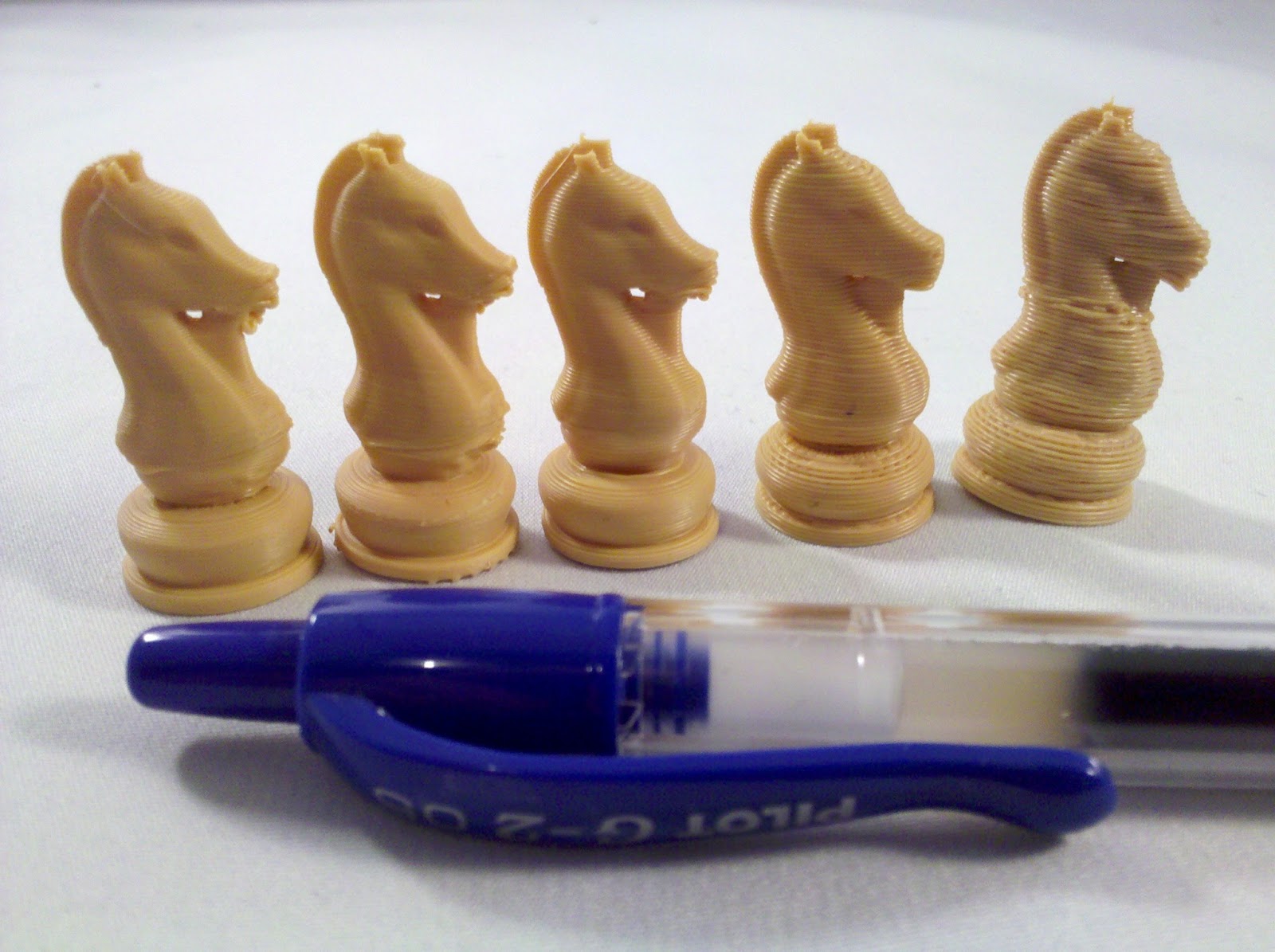
 This is the queen from the Steampunk Robot Chess set by Dutch Mogul, a set that I want to print soon to add to my collection. I figured this one had enough detail to tell me what I wanted to know. The one on the left (that I didn't finish cleaning the black out of the nozzle before printing) is printed at 0.35mm layers, the one on the right is 0.15mm. I wanted to see if you could smooth thick layers away. So I heated the acetone, loaded the ladies, and dipped them in the fog for a few minutes.


There's a lot of talk about using an acetone vapor to smooth ABS prints so I thought I'd try it out. But instead of getting a presto steamer (tho I may try that one day) I decided to construct my own.

- Candle warmer, $2.50 at a Thrift Shop, $5 new.
- Wide mouth canning jar
- Lid for regular mouth canning jar
- Wire coat hanger
- SteelStick bonding epoxy putty stuff, $10 at Wal-Mart.
- Willing subjects to be tested on
Canning jars we have just lying around and since acetone doesn't effect glass that's what I'd be using. I tested the candle warmer and with nothing on it it gets up to about 110C so I figured it would work for this. But I couldn't use hot glue or superglue because acetone does dissolve that, so I had to find something that would work. So it's time to play with a new material.

Epoxy brand SteelStick. Just cut off what you need, kneed it until it's a uniform color, mould it, and let it set. Only thing is this stuff stinks to high heaven. Be sure you're near an open door or window which you should be anyways because, you know, ABS, acetone, yeah. I also cut notches in the small jar ring to allow the acetone to flow under it freely when this is done. Then I stuck the lid to the ring metal side up and cut the coat hanger and stuck it to the sides of the ring with the epoxy.

Thanks helping hands. next time around I'm going to punch holes or ridges or something in the ring and lid first because the extra width to the ring caused me to crack the jar when I tried putting it in.

Oops. I guess that means I'll have to try again if I want to do this more after this. The top is left intentionally open because the acetone will condense and drip if there's anything above it. Also, I really didn't need to do 3 wires coming up since I had the ring, I just need a handle to pull it up by. Things to remember for version 2 if there ever is one.
Now, on to the victims.


0.15 on the left this time, sorry about the confusion. The layers in the 0.35mm queen are still apparent, tho it is smoother, but there are parts of the 0.15mm layered ones that smooth out so smooth that it looks molded, particularly at the bottom. However, on the hat where the layer differences are very dramatic they are still apparent even at the 0.15mm layer height. But over all the effect is good and much more glossy.
At this point I just started throwing in anything I had around to see what would happen and to figure out how long to leave them in.

Acetoned on the left, plain on the right. Notice the glossy vs matte look. The smudge is because I left that one in the vapor for way too long. I wanted to see if it got any better and if the dramatic layers on top ever smoothed out and I can now say there is no appreciable difference to leaving the pieces in the vapor for any more than 2 minutes. Any longer and they become too soft to handle. Again, only put the parts in the vapor for 2 minutes or less, there is no benefit to leaving them in any longer.

Dual colored parts work just fine. In fact this one came out looking really good.

Vaporing a lithophane is actually a bad idea, tho because the glossy finish pics up reflections in the light in front of the lithophane ruining the effect. Won't be doing that again.

The piece on the left was submerged in the vapor for 1 second. When that vapor is going it starts working quick, no messing around.

However, it doesn't effect the assemble-ability of a whole chess set (I had an extra black hero).
Not sure if I'm going to make this a habit. it's neat, but 0.15mm layers are already really smooth. All this does is make them... shinny. Which is okay if that's the look you're going for. I think I'm going to do it to the whole Steampunk Robot set when I print it, but then I'll probably put it away for a while. Unless I find a good reason to do it some more. But, hey, now I've got a bunch of junk to sell in my store. (I'm keeping the chess set.)
Saturday, February 16, 2013
Now I know where the value is
Restocking Glow-in-the-Dark 3D Hypnorings had a the black filament stop midway through the print.
 Actually, it's kinda of cool looking. But when I tried to figure out why the black stopped none of the usual suspects presented themselves. No knot in the spool, things were going good on that side. But if I did the load procedure no filament came out. So I pulled out the filament and found...
 One heck of a bulge. It couldn't go into the hot end so it just got caught there, the teeth cutting a groove into the filament above it. This was the Afinia value line black filament which has been in every other way spectacular, but now I know why the filament is cheaper. Not quite the same level of QC. But this is the first and only time I've had a problem with this filament so I'm still going to endorse it.


Wednesday, February 13, 2013
More PLA experiments
So far I've confirmed:
- PLA likes painter's blue tape. I'm using Duct brand.
- PLA can print cooler than ABS. I've been printing at 185 C.
- Printing without a cooling fan causes increased stringiness. What I printed to fix it didn't work, so for now I'm back to a fan on a box.
- You need to cool down or turn off your heated build plate. 70 is good for PLA. In skienforge and RepG means editing the "M109" line or making a new start.gcode and switching to it for PLA.
But with just these little tweaks printing in PLA has been a breeze. However, a timely comment set me on another set of experimentation:
I found that lower temperatures produced a sort of crystal lattice making the PLA seem more opaque, whereas higher the temperatures made the PLA more glassy and see through, but I only went to 240c. This is an area I am still to explore in more depth.
Well, let's give it a try. This time I'm going to print some TARDIS pendants that I can sell in the store when I'm done. I'm a little bit worried because I've heard that over heating the PLA can cause it to soften up the strand and jam the extruder. Here's hoping that doesn't happen. So starting at 185 and increasing the temperature 10C every iteration.
 From left to right the TARDIS pendants were printed at 185C, 195C, 205C, 215C and 235C. Or maybe it was from right to left? I'm not sure because it doesn't seem to make any difference what temperature I print at. This prints some fairly thin parts and even upon close inspection none of them are more transparent or shiny than any others. If this is true then maybe it only works when I don't have a fan blowing on the plastic so it cools down slower, but I think I'm willing to call this myth busted.
It's good to know I can print PLA as hot as I print ABS without problem, for small parts at least, but why would I if it doesn't make any difference?

It's good to know I can print PLA as hot as I print ABS without problem, for small parts at least, but why would I if it doesn't make any difference?
Tuesday, February 12, 2013
Print'n PLA
Thanks to Joseph Chiu I find myself in possession of a few 100 grams of PLA so, with my heated print bed out of commission until makerbot ships me the new part later this week I figure now is the time to try it out.
The difference with printing PLA is you want to print on blue painters tape,drop the extruder temperature from 235 to 185, open up the print area and get a fan blowing on nozzle head to cool the plastic as soon as it comes out. Easy, right?
 Actually, it's not that bad. But that's assuming all the horror stories I've heard about PLA being a pain to dial in aren't true. So first test print here we go...
 Woah, it worked. Just like that. (Sorry about the blue on blue.) Well, that was... easier than I thought. Let's try something a little bigger. Knowing I needed something better than a battery powered fan on a box I designed something to redirect my reversed fans on to the nozzle based on Lazy Man's fan guard (originally).
 Could not get a good picture of this thing. Maybe PLA doesn't photograph well. But it prints just fine.
Maybe it's just the plastic that Joseph Chiu sent me but this is really running counter to all the warnings and horror stories I've been hearing about switching to PLA. I guess PLA isn't anything to worry about. Plus not having to wait for the heated build platform means it gets to printing a lot faster. While I still don't think it's appropriate to do a 100% switch, it's definitely got it's applications. I'll follow this up with some experimentations later. Is there any PLA related experiments you'd like to see run?
The difference with printing PLA is you want to print on blue painters tape,drop the extruder temperature from 235 to 185, open up the print area and get a fan blowing on nozzle head to cool the plastic as soon as it comes out. Easy, right?


Maybe it's just the plastic that Joseph Chiu sent me but this is really running counter to all the warnings and horror stories I've been hearing about switching to PLA. I guess PLA isn't anything to worry about. Plus not having to wait for the heated build platform means it gets to printing a lot faster. While I still don't think it's appropriate to do a 100% switch, it's definitely got it's applications. I'll follow this up with some experimentations later. Is there any PLA related experiments you'd like to see run?
Thursday, February 7, 2013
Shells Vs Time
TheNewHobbiest asked me on twitter:
That's an excellent question. Let's find out.
 Fortunately I can find out without actually doing prints. The estimate function in ReplicatorG will give me something to compare.
The first subject I tested was Cinderella's Castle by SpaceCowboy850. I picked this one because I wanted something reasonably complex, but after I finished the tests I realized that they very small towers might actually fill in 100% with the loops. When that happens it won't put any more loops in that part adding no additional time. The second test subject was the Maltese Falcon by colinfizgig scaled down to be about the size of a chess piece. I picked this one because it's mostly round shape left lots of room for adding loops.
The procedure was simple. Slice the model with 0 extra shells and estimate the time, then slice the model for 1, then 2 then jump to 5 extra shells, estimating the time at each step and plot the results. Each pieces was made at 0.15mm layer height, 10% infill and 100mm/s feed rate with the altshell plug in turned on so the outside layer is printed slower than the rest of the layers. (That's more or less my default.) The results are as follows:
 At first glance results seem pretty linear. The castle actually looks like it's making a slight drop, which can be explained by the towers not being able to take any more shells. But strangely enough the slope in the Maltese Falcon's line is also slightly less than linear. This of course makes sense after some thought since each shell is smaller than the last one. Numerically this breaks down to, with the Maltese Falcon, an increase of 5 minutes for the first additional shell, 4 minutes of the next, and decreasing as more shells are added, with the Castle it was an additional 14 minutes for the first additional shell, 13 for the next and decreasing.
 While 5 minutes doesn't seem like much the thing to keep in mind that if you're printing a whole chess set those additional shells are adding 5 minutes per piece.
After all this I decided I wanted to how much time it would take to print with 0 extra shells but 100% infill, which produces a solid chunk of plastic, and the results were surprising. Estimate said the 100% filled Falcon would take 53 minutes and the 100% filled castle would take 3 hours 11 minutes. I had to check twice but for the Falcon after 2 or 3 shells there's no difference, time wise, to just fill the falcon in 100% with 0 extra shells. Clearly this isn't a universal rule because the castle did not have a similar result. So perhaps it's only small, solid, mostly round shapes? Either way if you're thinking you need to add more than 3 shells estimate it against 0 shells and 100% infill and determine if you can spare the plastic.
This was an interesting experiment, so thank you TheNewHobbiest for starting me on this journey. Knowing this will definitely change the way I print in the future. Probably. Maybe.
(PS. Updated the resolution comparison with a graph because I had excel open. Yup, it's a curve. You're welcome.)
@CymonsGames I was reading your blog post on printing with additional shells. Do more shells shorten or lengthen print times?
That's an excellent question. Let's find out.

The first subject I tested was Cinderella's Castle by SpaceCowboy850. I picked this one because I wanted something reasonably complex, but after I finished the tests I realized that they very small towers might actually fill in 100% with the loops. When that happens it won't put any more loops in that part adding no additional time. The second test subject was the Maltese Falcon by colinfizgig scaled down to be about the size of a chess piece. I picked this one because it's mostly round shape left lots of room for adding loops.
The procedure was simple. Slice the model with 0 extra shells and estimate the time, then slice the model for 1, then 2 then jump to 5 extra shells, estimating the time at each step and plot the results. Each pieces was made at 0.15mm layer height, 10% infill and 100mm/s feed rate with the altshell plug in turned on so the outside layer is printed slower than the rest of the layers. (That's more or less my default.) The results are as follows:
After all this I decided I wanted to how much time it would take to print with 0 extra shells but 100% infill, which produces a solid chunk of plastic, and the results were surprising. Estimate said the 100% filled Falcon would take 53 minutes and the 100% filled castle would take 3 hours 11 minutes. I had to check twice but for the Falcon after 2 or 3 shells there's no difference, time wise, to just fill the falcon in 100% with 0 extra shells. Clearly this isn't a universal rule because the castle did not have a similar result. So perhaps it's only small, solid, mostly round shapes? Either way if you're thinking you need to add more than 3 shells estimate it against 0 shells and 100% infill and determine if you can spare the plastic.
This was an interesting experiment, so thank you TheNewHobbiest for starting me on this journey. Knowing this will definitely change the way I print in the future. Probably. Maybe.
(PS. Updated the resolution comparison with a graph because I had excel open. Yup, it's a curve. You're welcome.)
Friday, February 1, 2013
Zeni Kinetic, Competitive, Local Made Filament
Just a quick heads up. There's a company from here in Utah that is entering the Filament game. Not the filament distribution game, the filament manufacturing game. Zeni Kinetic has their own production facilities right here using a top secret process to produce filament at prices competitive to buying your filament overseas. They're just starting out but I've decided to put them in the side bar and will update you all with the results of their filament when I get some to try out.
Keep an eye on Zeni Kinetic.
Keep an eye on Zeni Kinetic.
Wednesday, January 30, 2013
What's your resolution?
A lot of talk is made about resolution in 3D printing. What that means is the thickness of the layers. Individual layers are drawn in a continuous line so each layers doesn't really get any more detail than the next one. However, being able to stack more layers makes it harder to see the individual layers resulting in a better print at the cost of taking longer.
A recent conversation with one MattF in the comments made me want to show the effect that thinner layers have and show off how thin I've been able to get my prints. It's not earth shattering by any means, there are people doing much more impressive feats, but I think this will be educational.

A recent conversation with one MattF in the comments made me want to show the effect that thinner layers have and show off how thin I've been able to get my prints. It's not earth shattering by any means, there are people doing much more impressive feats, but I think this will be educational.
Wednesday, January 23, 2013
Filament by the foot
 Friend of the blog and fellow 3D printer Joseph Chiu has decided to plunge into filament sales. If you've ever wanted a color but didn't want to commit to a full kilogram he's selling 100g bundles of ABS or PLA in many colors so you can test it out before you commit to the big buy. 100kg is plenty to print off a Pocket Tactics army. I've been using his filament for a while. It's a little thinner than the stuff you get from other places so make sure you have a spring loaded extruder and have set your filament diameter appropiately. But it's consistent and good quality.
For now he's selling on Tindie while he gets his storefront up and running, but feel free to buy him out of stock and try out those colors you've always wanted to. Go give Joseph your business and get some filament.
Subscribe to:
Posts (Atom)